ACETRA Zwolle Project: Part Two
Project Location: Zwolle, the Netherlands
Project Date: Summer 2021
With the help of BIM technology, the Acetra team works together with architects and contractors to create a modern design that blends seamlessly with its traditional surroundings.
- Case Study
- Client: ACETRA
- Country: Serbia
- Type: CLT, Wood Framing, Residential & Commercial Construction

- Janko Maksimovic
Project Manager, Designer, Partner - Date: May 2022
Every construction project comes with its own unique set of demands.
For some, it’s the challenge of creating something entirely new — an innovative structure meant to push the limits of modern design. For others, it’s more about paying homage to a traditional aesthetic and tried-and-true building methods.
And for a select few? It’s about accomplishing both—no easy task, but one that can be done with the right team for the job.
“During the development of this project, we worked very closely with all the other participants,” says Janko Maksimovic, project manager, designer, and partner at Acetra, the company that designed the structural components for the build. “From the architects to the electrical engineers and contractors, it was important that we all collaborated from the beginning to create a design that met all the requirements of this unique project.”
Those requirements were very specific to the site itself. The original structure had been demolished but sat between three existing buildings in the historic part of Zwolle in the Netherlands. This location meant the new building had to meet the aesthetic guidelines and blend seamlessly with the surrounding historical architecture and fit precisely into the existing footprint.

So, how was the final design created? Collectively.
“The architects and engineers started the project, and then we spoke with them to collect input data and all the information we needed about the layout of the space, including foundation specs, plumbing installation, and electrical designs,” explains Maksimovic. “From there, we started working on the structural systems and figured out how the building would stand up.”
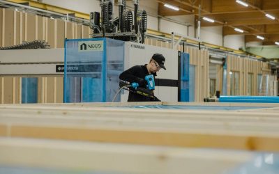
Using 2D, prefabricated, cross-laminated panels — a super-strong product that’s a smart option for structural walls, sheer walls, roof slabs, and more — the team created a unique plan for the three-story residential/commercial structure in 3 steps.

Step 1: Complete Preliminary Drawings
While the project architects were tasked with designing a structure that matched the traditional buildings positioned to the left and right, the Acetra team was responsible for managing load tolerances and ensuring the façade layers could be attached safely.
“At the beginning, we made schematic drawings with preliminary designs and dimensions,” says Maksimovic, adding that this process typically takes about 1-2 weeks. “After that, we present to the clients and other engineers for feedback and changes.”
During this period, the entire team needed to agree on the structural system and how the structure will look by addressing:
- What elements will create the structure?
The finished structure is made from CLT walls and GL and steel columns. These elements take loads from horizontal building elements – CLT slabs and GL and steel beams.
- How will the floors be constructed?
The floors are made of heavy gravel and cement screed over CLT slabs. This makes bigger dead loads but helps with the vibration of long single-span slabs.
- How will the floors be supported?
The CLT slabs were supported directly on CLT walls or steel beams. Steel beams are hidden in floor layers and aligned on the bottom surface with visible CLT.
- Are there any safety restrictions?
To adhere to local regulations, most of the structure’s walls are 120 mm thick, but due to fire protection criteria, walls that are visible and exposed to fire from both sides are made of 160 mm wide CLT panels.
- Do acoustics need to be considered?
Acoustic requirements of the building were met with soundproofing stripes in the wall to slab joints and under steel brackets.
“Together with the architects and the ventilation, plumbing, and electrical engineers, we needed to structurally analyze every part of the project,” Maksimovic says, a process that can take up to another month.

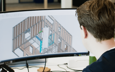
Step 2: Create 3D Models
Once the preliminary plans have been approved, the Acetra design team and the CLT engineers begin to lock in the structure and develop some of the first 3D models of the build.
“When we create that first 3D model, it includes all of the elements we agreed on with the other engineers,” Maksimovic explains. “This model isn’t the most detailed version but shows where the beams and walls are located, the thicknesses and sizes of the materials, etc. This allows the team to analyze the plan and double-check that everything’s okay.”
This is where Building Information Modeling (BIM) comes into play, specifically the Vertex BD software. “Shared modeling software is practically an international standard for communication between engineers,” says Maksimovic. “With the help of the Vertex software, we can import the models we get from them, share them with the entire design/build team, and make structural decisions to improve the project.”

Step 3: Address Challenges
In any construction project, challenges will come up. But with the use of shared BIM technology and a communicative team, you can make adjustments before ever breaking ground.
“There were two major challenges we needed to address during the design phase,” says Maksimovic. “First, because of the demolition of the buildings, we needed to move and change the shape of the building during the design phase. Specifically, there was a huge brick wall that they couldn’t demolish, so we needed to consider it in our design.
“Second, the electrical installation became more complicated because of the CLT panels. The client wanted to see the panels inside the structure (in other words, there was no drywall over the interior panels), so we had to create detailed cuts for the electrical installation and cables. Fortunately, Vertex is equipped with modeling options that made accounting for electrical cuts quite easy once we made the adjustments. This design feature will be incredibly valuable for us when working on future projects.”
In our next post, we’ll discuss the assembly process and how the detailed design helped the team execute a smooth build.

Related stories
Neco Elements Brings New Efficiency to Timber Construction
Neco Elements is transforming timber construction in Finland with innovative prefabricated elements that bring speed, quality, and cost-efficiency. Founded in 2024, the company combines decades of expertise with one of the country’s largest production facilities—using Vertex BD to ensure precise and seamless prefab production.
Helena Lidelöw: Steering VBC to global success with Vertex BD software
VBC grows with a core strategy centred on customisation and flexibility in Vertex BD, guided by Helena Lidelöw.
The three questions that shaped Ecohuis success in modular
Ecohuis, the leader in the Belgian modular home market, has shaped their success by focusing on three critical questions.
